Tag: l1 cache

  • Shared Memory Machine Model (notes)

    Shared Memory Machine Model (notes)

    You need to take away the following two themes for shared memory machine model:

    • Difference and relationship between cache coherence (dealt with in hardware) and cache consistency (handled by the operating system)
    • The different memory machine models (e.g. dance hall, symmetric multiprocessing, and distributed shared memory architecture)

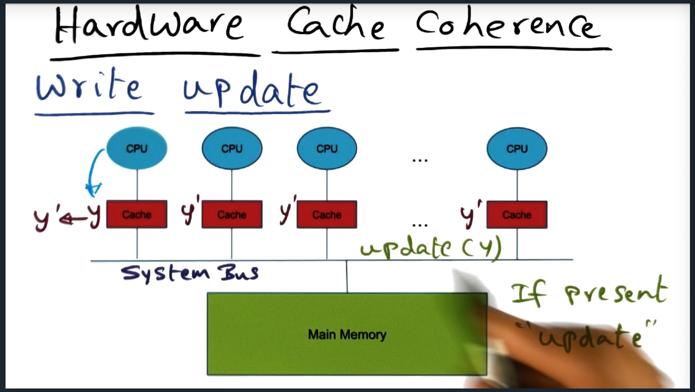
    Cache coherence is the promise delivered by the underlying hardware architecture. The hardware guarantees employs one of two techniques: write invalidate or write update. In the latter, when a memory address gets updated by one of the cores, the system will send a message on the bus to invalidate the cache entry stored in all the other private caches. In the former, the system will instead update all the private caches with the correct data. Regardless, the mechanism in which cache is maintained is an implementation detail that’s not privy to the operating system.

    Although the OS has not insight into how the hardware delivers cache coherence, the OS does rely on the cache coherence to build cache consistency, the hardware and software working in harmony.

    Shared Memory Machine Model

    Summary
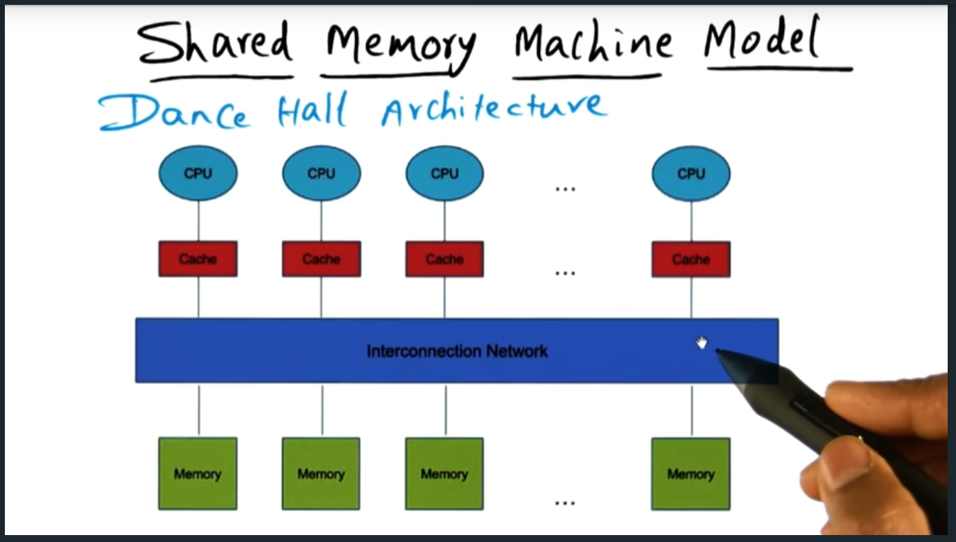
    Shared memory model - Dance Hall Architecture
    Shared memory model – Dance Hall Architecture
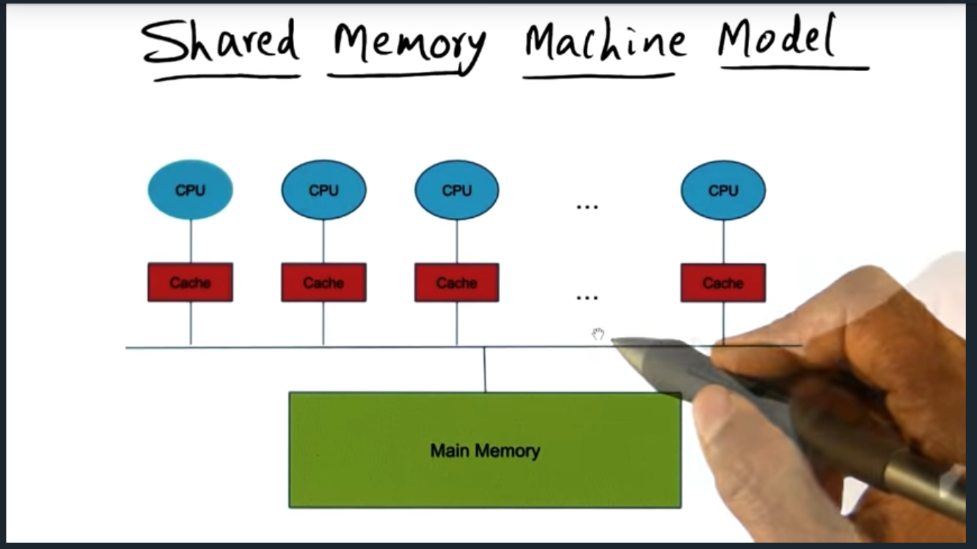
    Symmetric multiprocessing – each processor’s time to access to the memory is the same
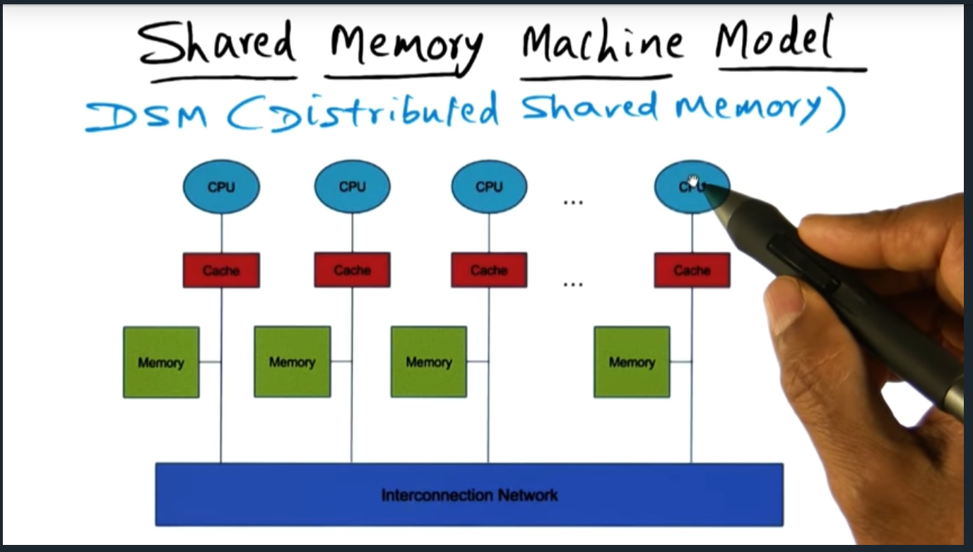
    Shared Memory Machine Model – each CPU has its own private cache and its own memory, although they can access each others addresses

    There are three memory architecture: dance hall (each CPU has its own memory), SMP (from perspective of each CPU, access to memory is the same as other CPU), and Distributed shared memory architecture (some cache and some memory is faster to access for a given CPU). Lecture doesn’t go much deeper than this but I’m super curious as to the distributed architecture.

    Shared Memory and Caches

    Summary

    Because each CPU has its own private cache, we may run into a problem known as cache coherence. This situation can occur if the caches tied to each CPU contain different values for the same memory address. To resolve this, we need a memory consistency model.

    Quiz: Processes

    Summary

    Quiz tests us by offering two processes, each using shared memory, each updating different variables. Then the quiz asks us what are the possible values for the variables. Apart from the last one, all are possible, the last one would break the intuition of a memory consistency model (discussed next)

    Memory consistency model

    Summary

    Introduces the sequential consistency memory model, a model that exhibits two characteristics: program order and arbitrary interleaving. This Isi analogous to someone shuffling a deck of cards.

    Sequential Consistency and cache coherence (Quiz)

    Summary

    Cache Coherence Quiz – Sequential Consistency

    Which of the following are possible values for the following instructions

    Hardware Cache Coherence

    Summary
    Hardware Cache Coherence

    There are two strategies for maintaining cache coherence. Write invalidate and write update. In the former, the system bus will broadcast an invalidate message if one of the other cache’s modifies an address in its private cache. In the latter, the system must will send an update message to each of the cache’s, each cache updating it’s private cache with the correct data. Obviously, the lecture oversimplifies the intricacies of maintaining a coherent cache (and if you want to learn more, check out the high performance computing architecture lectures — or maybe future modules in this course will cover this in more detail)

    Scalability

    Summary

    Scalability – expectation with more processors. Pros: Exploit Parallelism. Cons : Increased overhead

    Adding processors increase parallelism and improves performance. However, performance will decrease due to additional overhead of maintaining the bus (another example of making trade offs and how nothing is free).

  • A brief introduction to cache organization

    As a software programmer, I always had a vague understanding of how an operating system fetches data from memory.  At an abstract level, I understood that a processor requests data from the memory controller, sending a message (with the memory address encoded) across the bus.

    But I learned recently that in addition to the system’s physical memory—the same memory I used to squeeze into the motherboard when installing RAM—there are multiple hardware caches, completely abstracted from the programmer.

    These caches sit between the processor and main memory, called: L1 cache and L2 cache and L3 cache.  Each cache differs: in cost, in size, and in distance from the CPU. The lower the digit, the higher cost, the smaller in size, and the closer it sits to CPU.  For example, if we compare L1 and L2 cache, L1 costs more, holds less data, and sits closer to the processor.

    When the processor wants to retrieve data from memory, it sends a request first lands in L1 cache’s world.  If L1 has that memory page cached, it immediately sends that data back to the processor, preventing the request from unnecessarily flowing towards the memory controller.  This pattern of checking local cache and forwarding requests repeats until the request eventually reaches the memory controller, where data is actually stored.

    The further we allow the CPU’s request to travel down the bus, we penalize the CPU, forcing it to wait, like a car at a stop sign, for longer cycles. For example, the CPU waits 4 cycles for L1 cache, 12 cycles for L2, 36 cycles for L3, and—wait for it—62 cycles when accessing main memory.  Therefore, we strive to design systems that cache as much data as possible and as close to the CPU, increasing overall system performance.

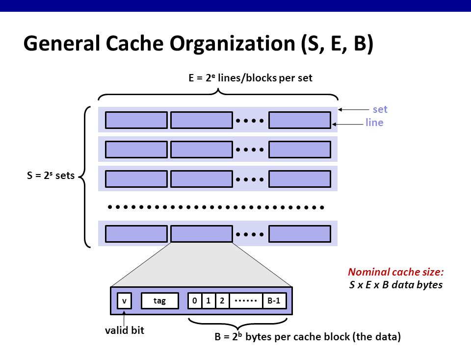
    We break down a cache into the following components:

    • Blocks
    • Lines
    • Sets
    • Tag
    sets, lines, blocks
    Cache organized into sets, lines, and blocks

    As you can see from the image above, we organize our cache sets (S), lines (L), and blocks (B).  One block of data represents 8 bits (1 byte) and every block of data is represented by a physical memory address. For example, the memory address 0x0000 may store 010101010 and 0x0001 may store 01110111 another.  We group these blocks together into a line, which store sequential blocks.  A line may store two or four or eight or sixteen bytes—it all depends on how we design the system.  Finally, each line belongs to a set, a bucket that stores one or more lines.  Like the number of bytes a line stores, a set can store one or two or three or forty—again, it all depends on our design.

    Together, the total number of sets, number of lines, and number of bytes determine the cache’s size, calculated with the following formula: cache size = S x E x B.

    In the next post, I’ll cover how a cache processes a memory address, determining whether it retrieves memory from cache or forwards the request to the next cache (or memory controller).